A three-dimensional nonlinear structural analysis program written in Python. The software is currently underdevelopment. The features of the software are listed below. The website will be frequently updated to provide more information regarding the software. So, stay tuned!
List of Load Analysis Cases
- Linear Static Analysis (Self-Weight Loading and Auto Lateral Load Patterns)
- Nonlinear Static Analysis (Force and Displacement Controlled)
- Modal Analysis (Eigenvalue analysis with custom mass source definitions)
- Buckling Analysis
- Multi Directional Response Spectrum Analysis (CQC, SRSS, ABSSUM )
- Multi Directional Response History Analysis
- Uncoupled (Modal)
- Coupled Linear
- Coupled Nonlinear
- Damping: Modal Superposition, Rayleigh, Mass and Stiffness Proportional
- Option to continue/define a Previous Load Case
List of Element Types
- Truss (P-Δ and Corrotational Transformation)
- Euler-Bernoulli Beam-Column (P-Δ and P-Δ + P-δ)
- Timoshenko Beam-Column (P-Δ and P-Δ + P-δ)
- ZeroLength (Linear and nonlinear material assignment)
- Link (Linear and nonlinear material assignment and P-Δ)
- 2D (Membrane, Plate, Shell) and 3D Solid elements are under development
List of Available Material Laws
- Elastic
- TensionOnly
- CompressionOnly
- Bilinear (Elasto-plastic)
- Bilinear (Elastic)
- Menegotto-Pinto (inluding asymmetric, isotropic and kinematic hardening parameters)
- ViscousDamper (Maxwell material with nonlinear velocity exponent)
- BilinearOilDamper (Maxwell material with bilinear velocity relation)
Load Combinations
- Linear
- Envelope
- SRSS
Frame Object Assignments
- Releases with or without stiffness
- End Offsets in all directions
- Automated member division
- Local Axis Rotation
Frame Loading
- Point Load (Force and Moment)
- Uniformly Distributed Loading
- Trapezoidal Distributed Loading
- Temperature Loads (Axial and Flexural)
- Load Assignment in Global and Local Coordinates
- Line Object Loading Option
Restraints and Coonstraints
- Inclined Support (through orientation of ZeroLength member transformation)
- Equal DOF
- Rigid Diaphragm
VISUALIZATION
Detailed post-processing graphics, such as visualization of model, loading and analysis outcomes, displaced shapes and internal force diagrams are available. The figures below illustrate the model of a 2-story steel-moment resisting frame building with irregular plan dimensions.
Rigid Diaphragm and Area to Frame Loading
Figure 1 shows load distributions of SUPERDEAD load case, which is assigned to area objects. The loads are transferred in two-way to the frame objects. Rigid Diaphragm Constraints are defined at both floor levels. Node numbers 37 and 38 are the master-nodes.

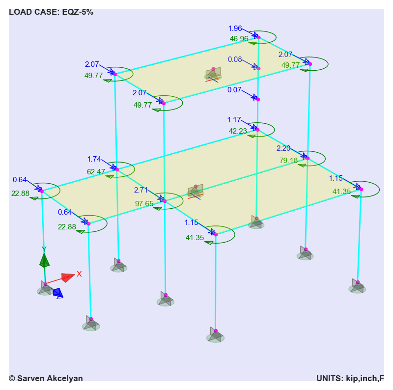
Auto Lateral Load Pattern: Equivalent Static Earthquake Load Procedure per NBCC-2015
Figure 2 shows seismic load distribution per equivalent static procedure of NBCC 2015 (National Building Code of Canada) in Z-direction. This loading case includes accidental eccentricity. The resulting lateral forces and torsional moments are assigned to each node.
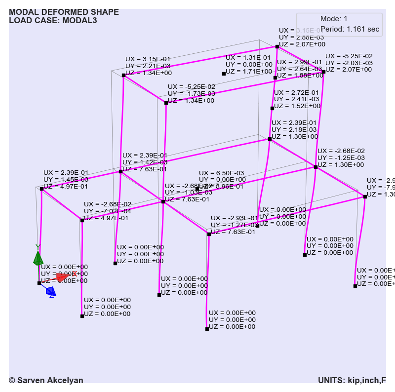
Modal Analysis and Its Deformed Shape
Figure 3 displays first mode deformed shape obtained from eigenvalue analysis. Displacements at each node are also shown. Multiple modal analysis with different mass source combinations are possible.
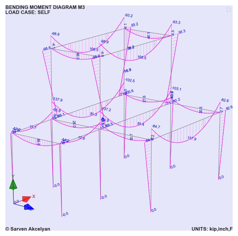
Internal Force Diagrams
Internal force diagrams can simply be displayed with members’ peak and end values. For instance, Figure 4 shows bending moment diagram of the 2-story building under self loading.
Three Dimensional Object View
Three-dimensional view options is useful in visualizing member dimensions. Figure 5 shows three-dimensional view of W-shape beams and columns.

MORE TO COME!!!!

